
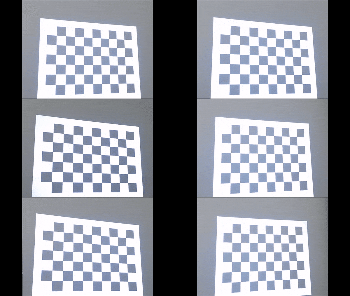
- Projected checkerboard image
- Getting the 3D-2D coordinates of the checkerboard corners
- Rotate 3D points using eigenvectors
- Geometric interpretation of eigenvectors and Singular Value Decomposition (SVD)
- Projector and Kinect depth camera extrinsics
Combining a Microsoft Kinect with a projector enables augmented reality (AR) applications. This requires system calibration. Existing methods, such as RGBDdemo and KinectProjectorToolkit, require either printed checkerboard patterns or a large room to calibrate the Kinect depth and color cameras and the projector.
In many AR applications, the relative rotation and translation between the Kinect and the projector are fixed. As shown below, we mount them together so that their fields of view (FOVs) overlap.
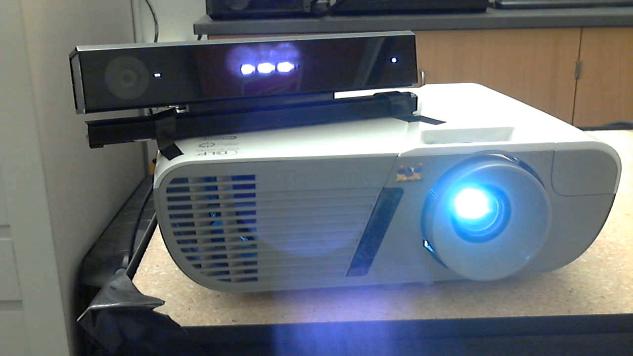
In this tutorial, we calibrate the system using Zhang’s method without a printed checkerboard pattern or a large room. We project a checkerboard pattern onto a flat white wall, then move the mounted Kinect-projector pair to capture images from at least three different poses, as shown in the demonstration above.
The rest of this tutorial focuses on calibrating the intrinsic parameters of the projector and the extrinsic parameters between the projector and the Kinect depth camera. The intrinsics of the Kinect color and depth cameras can be obtained from the Kinect for Windows SDK or calibrated using a printed checkerboard.
Projected checkerboard image
We first generate a checkerboard image pattern using OpenCV:
Mat generateCheckerboardImg(Size imgSize, Size boardSize, vector < Point2f > & cbPts2d) {
  int offset = 50; // OpenCV requires white borders around the checkerboard pattern

  // checkerboard image
  Mat imgCheckerboard(imgSize, CV_8UC3, Scalar::all(255));

  // block size
  int squareWidth = floor((imgSize.width - 2 * offset) / boardSize.width);
  int squareHeight = floor((imgSize.height - 2 * offset) / boardSize.height);

  // block color
  unsigned char color = 1;

  //! The order must be consistent with OpenCV order:
  //row first then column, each row sweep from left to right
  for (int y = offset; y < imgSize.height - offset; y = y + squareHeight) {
    color = ~color;
    if (y + squareHeight > imgSize.height - offset) {
      break;
    }
    for (int x = offset; x < imgSize.width - offset; x = x + squareWidth) {
      color = ~color;
      if (x + squareWidth > imgSize.width - offset) {
        break;
      }
      // save checkerboard points
      if (x > offset && y > offset) {
        cbPts2d.push_back(Point2f(x, y));
      }
      // color the block
      Mat block = imgCheckerboard(Rect(x, y, squareWidth, squareHeight));
      block.setTo(Scalar::all(color));
    }
  }
  return imgCheckerboard;
}
The code is inspired by Haris
where boardSize contains the number of squares in row and column, cbPts2d stores a list of inner corners of the checkerboard and is given by:
where $\mathbf{q}_i = [ u_i, v_i ]$ is the 2D coordinate of the $i^\text{th}$ checkerboard corner in the projector image space and the number of detected inner corners is $N$, recorded by cbPts2d.size().
The generated checkerboard image is shown below. OpenCV’s findChessboardCorners requires white borders around the checkerboard pattern, so we add an offset in both the x and y directions.
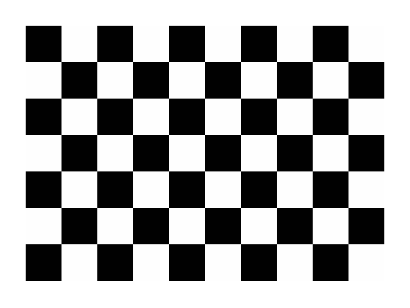
We project this checkerboard onto a flat white wall and capture depth and color frames using the Kinect. Zhang’s method requires at least three different poses.
Getting the 3D-2D coordinates of the checkerboard corners
Given a Kinect-captured color checkerboard image, we first extract the 2D checkerboard corners $\mathbf{P}^{\text{2d}}_{\text{c}}$ using OpenCV’s findChessboardCorners. Then $\mathbf{P}^{\text{2d}}_{\text{c}}$’s corresponding 3D coordinates in the Kinect depth camera’s view space can be queried from the Kinect-captured depth image using $\mathbf{P}^{\text{2d}}_{\text{c}}$ and Kinect Windows SDK v2.0: CoordinateMapper:
where $\mathbf{x}_i = [ x_i, y_i, z_i ]$ as the corresponding 3D coordinate of $\mathbf{P}^{\text{2d}}_{\text{c}}[i]$. Note $\mathbf{P}^{\text{2d}}_{\text{c}}$ is only used to extract $\mathbf{P}^\text{3d}$ from the Kinect-capture depth image in this article, but if you want to calibrate Kinect color camera keep $\mathbf{P}^{\text{2d}}_{\text{c}}$ for Zhang’s method.
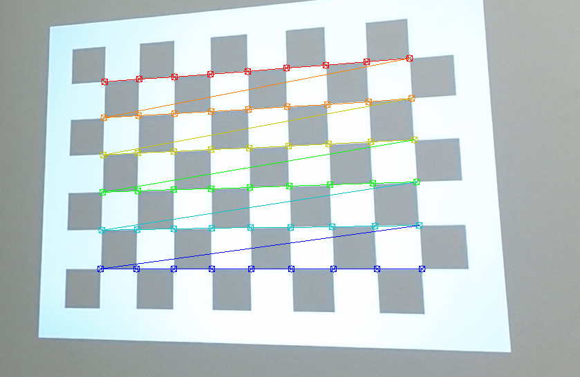
Make sure the order of $\mathbf{P}^{\text{2d}}_{\text{c}}$ in the image above matches the order of those in $\mathbf{P}^\text{3d}$, basically the corner colors represent the order of the points in $\mathbf{P}^{\text{2d}}_{\text{c}}$, red is the first element in $\mathbf{P}^{\text{2d}}_{\text{c}}$ vector and dark blue is the last one.
Since $\mathbf{P}^{\text{2d}}_{\text{p}}$ is given by generateCheckerboardImg, now we have the 3D-2D point pairs ($\mathbf{P}^\text{3d}$ and $\mathbf{P}^{\text{2d}}_{\text{p}}$) to calibrate the projector intrinsics and extrinsics. But if you send the point pairs directly to OpenCV’s calibrateCamera, it will raise an exception, because this function requires that the Z values of objectPoints to be zeros, i.e., Zhang’s method assumes all objectPoints reside on the XY plane of checkerboard’s object space, thus the 3x4 projection matrix $\mathbf{K[RT]}$ can be reduced to a 3x3 homography $\mathbf{H}$.
The plotted points $\mathbf{P}^\text{3d}$ lie on a plane, but their Z coordinates are nonzero because they are expressed in the Kinect depth camera’s coordinate system rather than the projected checkerboard’s coordinate system.
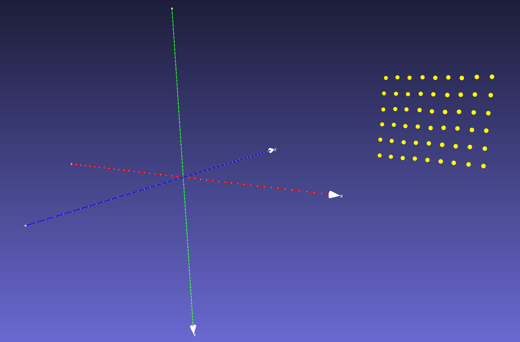
For a printed checkerboard, the 3D corner coordinates are known from the board’s geometry. A projected checkerboard is distorted by perspective projection, and its geometry changes with the pose of the projector-Kinect pair relative to the wall. Each projected pattern therefore has an unknown scale and shape.
Rotate 3D points using eigenvectors
One workaround is to estimate a rotation and translation between the Kinect depth camera’s view space and the checkerboard’s object space and then transform $\mathbf{P}^\text{3d}$ to the canonical view, so that they reside in the Kinect depth camera’s XY plane (centered at the origin). This needs the checkerboard plane parameters. Luckily, since we know that $\mathbf{P}^\text{3d}$ has a planar shape, its parameters can be estimated using one the three methods below:
- choose any three non-collinear points in $\mathbf{P}^\text{3d}$ to calculate the plane’s normal (i.e., Z axis direction) and X, Y axes directions in the checkerboard’s object space.
- use all the points in $\mathbf{P}^\text{3d}$ to fit a plane by minimizing the least squares error, this will give us plane normal (Z direction). Then choose any two points in $\mathbf{P}^\text{3d}$ to calculate X (or Y) axis direction and the other axis is the cross product of normal and X (or Y), i.e., Y =
cross(Z, X) for a right-handed orthonormal frame. - use the eigenvectors of $\mathbf{P}^\text{3d}$’s covariance matrix as the plane’s XYZ axes.
Here are the pros and cons. For method 1, which three points should we choose to estimate the plane? The same question applies to method 2 too, which two points should we use to estimate X (or Y) axis? We prefer method 3 since it considers all points in $\mathbf{P}^\text{3d}$ and it is simpler.
Geometric interpretation of eigenvectors and Singular Value Decomposition (SVD)
The two principal directions with the largest variance span the fitted checkerboard plane; the remaining direction is its normal.
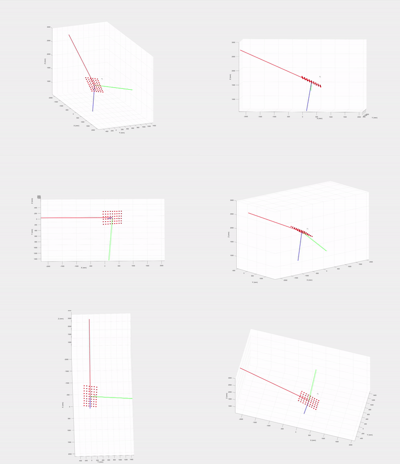
Use a $3\times N$ matrix with one measured point per column, $\mathbf{P}=[\mathbf{x}_1,\ldots,\mathbf{x}_N]$. Its centroid and centered coordinates are
\[\boldsymbol{\mu}=\frac{1}{N}\mathbf{P}\mathbf{1},\qquad \mathbf{X}=\mathbf{P}-\boldsymbol{\mu}\mathbf{1}^{T} =\mathbf{P}\left(\mathbf{I}_N-\frac{1}{N}\mathbf{1}\mathbf{1}^{T}\right).\]The centering matrix acts on the right because points are columns. The covariance is $\mathbf{\Sigma}=\mathbf{X}\mathbf{X}^{T}/N$. If $\mathbf{X}=\mathbf{U}\mathbf{S}\mathbf{V}^{T}$, then $\mathbf{\Sigma}=\mathbf{U}\mathbf{S}^{2}\mathbf{U}^{T}/N$; the columns of $\mathbf{U}$ are the principal directions.
- Subtract the centroid from each measured point to form $\mathbf{X}$.
- Compute the SVD with singular values in descending order. The third column of $\mathbf{U}$ is the fitted plane normal.
- Choose the signs so that $\det(\mathbf{U})=+1$ (flip the third column if needed), then compute $\mathbf{P}_{\mathrm{obj}}=\mathbf{U}^{T}\mathbf{X}$. This expresses the centered points in a right-handed frame whose XY plane is the fitted checkerboard plane.
- Noise and surface nonplanarity leave small residual Z coordinates. Set the third row of $\mathbf{P}_{\mathrm{obj}}$ to zero to project the measurements onto the fitted plane before planar calibration.
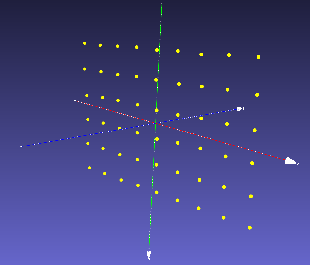
Consistent in-plane axis sign choices do not change the projector intrinsics; retain the same point ordering in the 3D and 2D correspondence arrays.
Finally, we have $\mathbf{P}^{\text{3d}}_{\text{obj}}$, the 3D coordinates in the checkerboard’s object space and $\mathbf{P}^{\text{2d}}_{\text{p}}$, the corresponding 2D coordinates in the projector image space to calibrate the projector intrinsics using calibrateCamera.
Projector and Kinect depth camera extrinsics
We can also obtain the relative rotation and translation $\mathbf{RT}$ between the Kinect depth camera and the projector by passing the calibrated projector intrinsics, the known Kinect depth camera intrinsics, the 3D checkerboard corners $\mathbf{P}^{\text{3d}}_{\text{obj}}$, the 2D corners in the projector image $\mathbf{P}^{\text{2d}}_{\text{p}}$, and the 2D corners in the Kinect depth camera image $\mathbf{P}^\text{2d}_\text{d}$ to OpenCV’s stereoCalibrate.
The calibrated projector intrinsic projection matrix
\[\mathbf{K}_\text{p} = \begin{array}{|l|l|l|} \hline 1227.8 & 0 & 450.9 \\ \hline 0 & 1214.9 & 606.1 \\ \hline 0 & 0 & 1 \\ \hline \end{array}\]projector distortion coefficients
\[\mathbf{Kc}_\text{p} = \begin{array}{|l|l|l|l|l|} \hline -0.1708 & 1.0518 & -0.0168 & 0.0065 & -2.8967 \\ \hline \end{array}\]projector-camera extrinsics
\[\mathbf{RT} = \begin{array}{|l|l|l|l|} \hline \mathbf{r}_1 & \mathbf{r}_2 & \mathbf{r}_3 & \mathbf{t} (\text{mm}) \\ \hline 0.9435 & -0.061 & -0.3256 & 177.72 \\ \hline -0.004 & 0.9807 & -0.1953 & -92.0386 \\ \hline 0.3312 & 0.1856 & 0.9251 & -21.0593 \\ \hline \end{array}\]